Why is my BCDC Alpha not charging from the vehicle?
This information is applicable to the following BCDC Alpha chargers:
- BCDC Alpha 25A DC Battery Charger (BCDC12025B)
- BCDC Alpha 50A DC Battery Charger (BCDC12050B)
WHAT DOES THIS LOOK LIKE?
If the BCDC Alpha doesn't detect an input source and there is no connection to the RedVision App, no LED’s will be illuminated indicating that that BCDC Alpha is in standby mode.
WILL THE BCDC ALPHA STILL CHARGE MY BATTERY IN THIS CONDITION?
Providing the solar input to the BCDC is adequate, it will continue to charge when connected to a solar panel that is in the sun. While there is an issue with the vehicle input, the BCDC will cease charging once the solar input voltage drops below 9V.
WHAT CAN CAUSE THIS FAULT?
When the vehicle input wire (red) is compromised from either of the following:
- Undersized cable
- Poor connections - such as loose or damaged terminal/connections
- Faulty fuse protection
WHY DOESN'T IT DISPLAY A FAULT CODE?
There could be an issue with the power supply such as:
- Input voltage present but is below turn on threshold
- Poor ground (earth) yet not severe enough to trigger a fault code
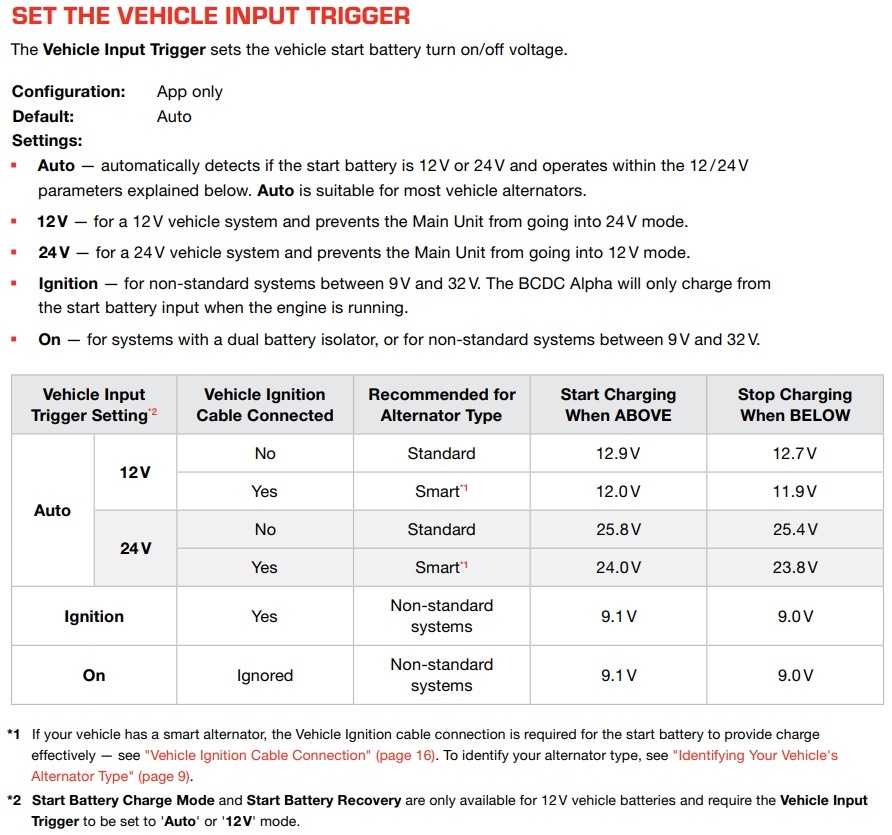
WHAT ARE THE TURN ON/OFF THRESHOLDS OF THE BCDC?
The turn on/off thresholds are determined by what the Vehicle Input Trigger setting is set to.
See Vehicle Input Trigger details below:
HOW TO DETERMINE THE CAUSE OF NO CHARGING FROM THE VEHICLE?
To determine the cause of this condition, it will require diagnostic testing. REDARC recommends seeking the support of an installer where possible, however please see below a list of the common causes and repairs.
A) FAULTY FUSE PROTECTION
As the BCDC Alpha draws a continuous high amount of power (current), choice of fuse protection is critical. Unsuitable fuse protection can function correctly initially; however it may fail over time. Blade fuses and circuit breakers are the most common cause of issues resulting in either poor performance or intermittent operation.
Things to check:
- Locate and identify the fuse protection used between the starting battery and BCDC.
- Locate and identify the fuse protection used between the BCDC and the Auxiliary battery.
- Visual/physical checks:
- Check that all connections are clean and tight.
- Check all wiring lugs connections are in good condition.
- Ensure the fuse and lugs are free from corrosion and debris. - Once the issue has been located, whether a faulty fuse and/or poor wiring connection, rectify the issue and recheck operation.
B) LOOSE CONNECTION AT THE START BATTERY TERMINAL/FUSE HOLDER OR LOOSE GROUND CONNECTION AT THE BCDC
The most likely cause is due to poor power supply created by a loose or poor ground circuit.
Things to check:
- Ensure connection points are clean, not damaged or loose.
- Remove battery terminal and ensure a clean surface area is provided for the terminal.
- Inspect the ground wire (-) to ensure it has a suitable ground connection, such as a terminal attached to bare metal (unpainted surface).
- Ensure each crimp connection is strong, a small tug on each wire can confirm this.
- Once all connection points have been addressed, re-check operation.
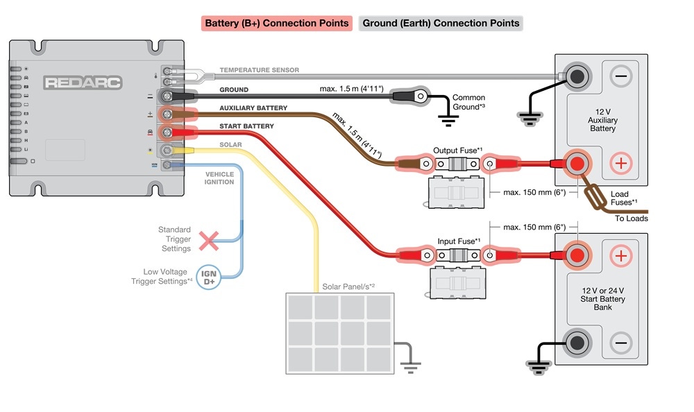
The below image shows a typical BCDC install. The diagram shows the typical connection points for an installation.